09.08.23
| Downloadable

With heat treating, we push metallurgical limits to maximize material performance and prepare parts for a life of heavy service. But it doesn’t come without risk. Hypervigilance around the conditions that cause cracking from design to production is key for preventing defects that compromise critical parts.
In this guide, we delve into the various factors contributing to crack formation and how to effectively manage risk of cracking during heat treatment.
Cracking most commonly occurs at the surface of a part when stresses at the surface become greater than the strength of the hardened material. Surface stress builds during the transformative phases of heat treatment as part undergoes metallurgical changes, along with expansion and contraction in response to the heat. These conditions can be influenced by several factors, including part design and quench rate, and can easily be avoided.
More than any other material that’s commonly heat treated, tool steels have an enhanced risk of cracking during heat treatment due to their high hardenability. Understanding how to design tooling and dies for crack mitigation is vital for preventing part failure.
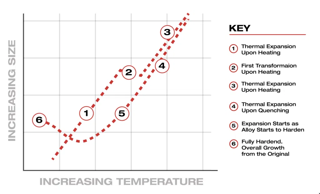
Thermal expansion is a physical phenomenon that occurs when parts undergo changes in size, volume, or shape in response to changes in temperature. This change in shape can cause detrimental stress on the part depending on how it’s designed.
When a substance is heated, its atoms gain energy, leading to an increase in their vibrational motion. As a result, the average spacing between the atoms tends to increase, causing the material to expand. Conversely, when the material is cooled, the decrease in particle energy leads to a contraction or decrease in volume.
The thermal expansion of materials is predictable, typically characterized by a coefficient of thermal expansion (CTE). The CTE quantifies the fractional change in length or volume of a material for each degree Celsius (or Kelvin) change in temperature. It is expressed in units of reciprocal temperature, such as meter per meter per degree Celsius (m/m/°C) or parts per million per degree Celsius (ppm/°C). Most hotwork tool steels expand and contract at 12.6×10^-6 m/m/°C.
The graph below demonstrates the direct relationship between the increased size of the part (or level of thermal expansion) and increased temperature.
Thermal conductivity also plays a role in determining how quickly a material gains or loses heat. Thin sections have a higher surface-to-volume ratio, which means they dissipate or absorb heat more rapidly than thick sections. As a result, thin sections are more prone to rapid temperature changes during heating or cooling processes.
H13 is a prime example of why thermal expansion calculations need to be made prior to producing a part. An H13 part that’s one meter in length will expand almost 13mm at the austenitizing temperature of 1029°C, a considerable amount that needs to be accounted for in the engineering of the part. How uniformly a part grows and contracts will also influence distortion and crack risk. The uniformity of thermal expansion or contraction throughout a part is crucial because uneven growth or shrinkage can cause increased internal stresses, leading to increased distortion and even cracking of the material during the quench portion of the heat treatment.
To learn more about design elements that affect this, skip to this section: design for crack prevention.
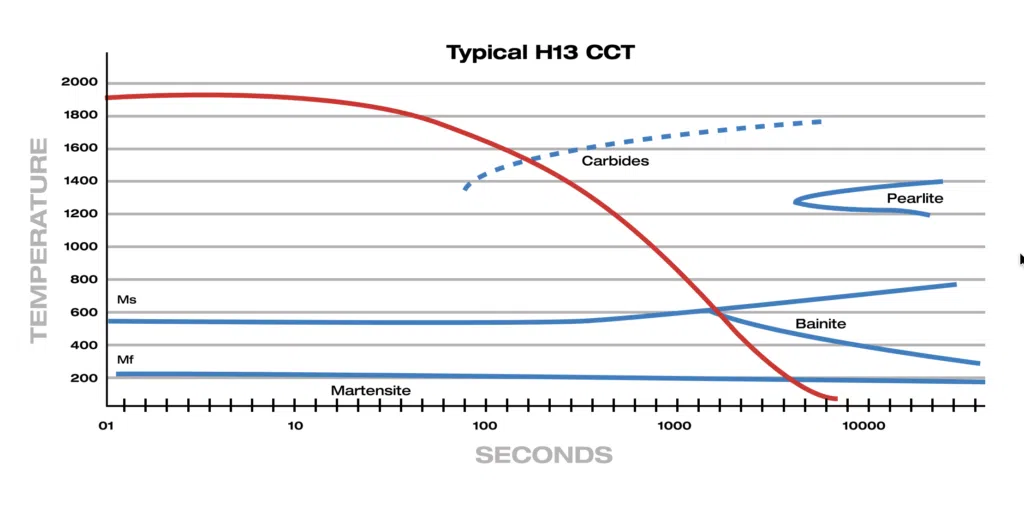
During quenching, a rapid cooling process, non-uniform metallurgical transformations can cause internal stresses to build up within the material. If these stresses exceed the material’s strength, cracks can form. This phenomenon is known as quench cracking and is a significant concern in heat treatment processes, especially for certain types of steels and alloys that are prone to this behavior.
Assuming the part has been designed with crack prevention in mind (and to prevent non-uniform distortion), the second line of defense for any part is to choose the right approach to heat treating. For materials like H13, the goal should be to minimize the formation of carbide and maximize the formation of martensite. As shown in the graph above, this can be achieved by a faster quench rate.
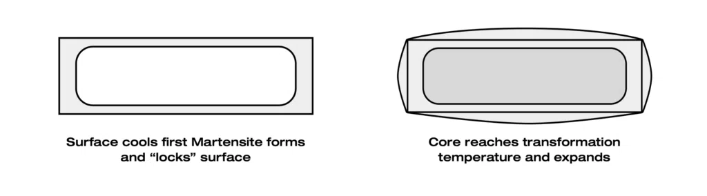
When designing a part for production, think of the part as a balloon. Increased heat causes a part to expand and reduced temperature will slow that expansion rate and eventually cause contraction. It’s important to consider how, exactly, your part cools. The surface of a part will cool at a much faster rate than the core, causing an uneven cooling rate.
The surface transforms into martensite rust and hardens out while the inside of the part is still at a higher temperature where no transformation has occurred yet. Once it transforms, it grows and creates the balloon effect. A part is more prone to cracking when it’s in this ballooned state because the surface becomes stressed from increasing internal pressure. When designing a part, it’s crucial to consider which elements might increase the risk of cracking during this stage of transformation.
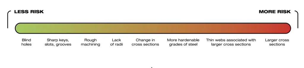
There’s no avoiding the “ballooning” of a part, this is a natural occurrence of heat treating. But there are certain elements to pay attention to when designing a part to better handle this transformation. The following list demonstrates design features that increase the risk of cracking during heat treatment, with larger cross section being the riskiest feature to incorporate in the design of a part.
In collaboration with North American Die Casting Association (NADCA), AST-Paulo helped define the latest design standards for engineers developing parts that require heat treatment. NADCA regularly publishes design standards for the die casting industry to improve the effectiveness and safety of parts. Here we cover several key recommendations outlined in NADCA 207 2022.
Thin webbed detailing on a die has a greater potential of developing into a sharp knife edge or burr, which are defects of the machining process. Thin webs, sharp knife edges, and burrs are problematic in heat treating because they’re significantly thinner than the rest of the part, causing different cooling and heating rates and higher risk of cracking. Thin webs should be removed from the design or increased in thickness to reduce risk of cracking.
Any sharp features will affect the integrity of the part when it’s ballooned during heat treatment. That means it’s crucial to avoid sharp corners. The official NADCA recommendation is to make inside radii no smaller than 0.25” or 5.0mm in large tooling to minimize risk of cracking. It’s also outlined that 0.120” or 3.0mm may be sufficient.
Tooling with complex geometries and large steps are at an especially high risk of cracking and may need even larger radii than what’s recommended above. Some tooling may require 0.500” or 13mm or greater.
When it comes to external radii on holes, there should be a minimum of 0.120” or 3mm chamfer to avoid a sharp corner at the surface of the hole.
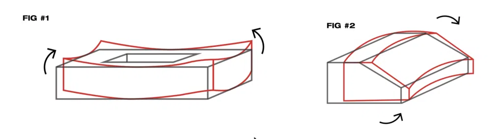
These images below show an effective design solution that graduates from the large portion of a part to the smaller portion. With the two distinct sizes and shapes at either end of the part comes a large disparity between heating and cooling rates. If the transition between the two sides were to be left as a sharp corner, a great amount of stress would build, along with the potential for cracking.
NADCA 207 2022 recommends that all “holes drilled prior to heat treat should have at least 0.24” or 6mm wall thickness between them,” however, “0.400” or 10mm is optimal.” Adhering to this standard will also help minimize thin webs or sharp knife edges from developing in the machining process.
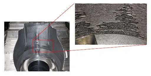
Rough machined tool surface with tearing and sharp steps are also problematic during heat treatment. It’s important for tooling suppliers to inspect the materials surface between cuts and verify that no tearing or sharp cuts are present before being sent for heat treatment. Below is an example of rough cuts and tearing on a part.
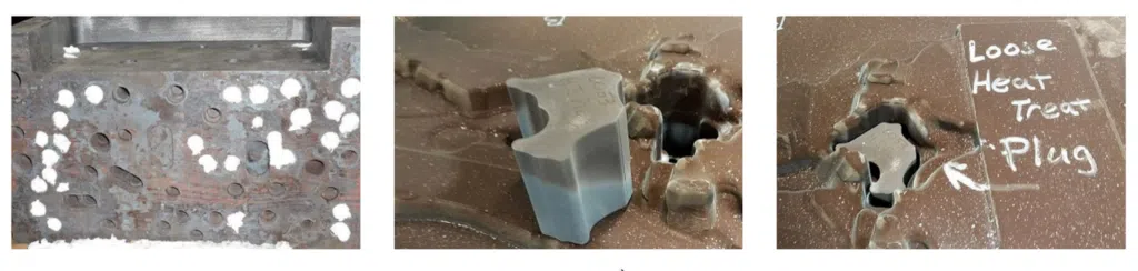
Packing holes, channels, and large gaps with furnace insulation or dummy blocks can help to even out the heat and cool rate on risky areas that are critical to the part’s function—such as thin cross section or small radii. Insulation can’t be used on a hot metal surface (the surface of the metal that will be exposed to liquid metal in the die casting process) but dummy blocks can. Below are pictures of how insulation and dummy blocks are placed into a part.
Finding an experienced heat treater is just as important as part design when it comes to crack risk mitigation. At AST-Paulo, we’ve worked with tooling suppliers across nearly every industry to develop tooling, engineered to withstand heavy production loads.

There’s no one size fits all approach for heat treating dies. Each project requires careful attention to detail in order to deliver the highest quality parts. At AST-Paulo, we have the capability to accommodate dies of almost all types and sizes. Our in-house cranes and rigging equipment allow us to move extra large and heavy parts safely throughout our facility, and we meet all NADCA guidelines for high-pressure die casting dies. Our advanced data collection and photo capture of tooling throughout the heat treating process provides greater traceability and quality control in our processes.
Partner with AST-Paulo on your next project to mitigate crack risk and heat treat your part with a greater level of scientific certainty. Request a quote to get started on your next project.

